For this group project, we are planning on using Nintendo's "Wiimote" as an input device to use inside Houdini. Utilizing CHOPs, we plan on controlling geometries inside the viewport in dynamic or game simulations. Later, we want to capture and record these movements and render them out in a sequence.
 List of our Materials
* A PC with Windows XP
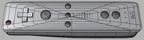
* A Wiimote
* Kensington Bluetooth USB Adapter 2.0
* Infared Sensor Bar
Get the Bluetooth DriverBefore even thinking about Houdini, we need to get the Wiimote working on the PC. Depending on the bluetooth dongle you must use specific drivers for this thing to work. Since we are using the Kensington USB 2.0 Adapter, we must use the driver below. So before installing the drivers that are packed in with the dongle, make sure to check which driver you need to use for the Wiimote HERE.
Download the Driver Here: KensingtonBTW_4.0.1.2400.zipConnect the Wiimote to the PC
After installing the compatible device drivers, do the following:
* Double-click the Bluetooth tray icon.
* Tell it to search for bluetooth devices
* Press and Hold the 1 and 2 buttons on the Wiimote
* It finds the Nintendo Wii Remote (Nintendo RVL-CNT-01)
* Click on the icon labeled "Nintendo RVL-CNT-01" to select it and then clicked "Next"
* Click the button labeled "Skip Pairing"
* "Use a Bluetooth enabled mouse, keyboard, or other interface device" with a "checked" checkbox
* Click Finish
Testing it Out!After all that, I found a neat little program called WiinRemote on
http://onakasuita.org/wii/. It is a Wiimote Driver that basically lets you use the Wiimote as an input device. You can map any keyboard and mouse buttons onto the Wiimote buttons and motions. You can even set up the Nunchuck attachment and use the analog as the cursor and utilize its Z and C buttons! So this is the key. Now that we have got it working on the PC, we can bring it in Houdini!
Download WiinRemote Here: WiinRemote_v2007.1.13.zipChoosing a WiiMote Software
There are many other software packages that are capable of driving the WiiMote, so search
around or follow the links below, don't limit yourself to this one.
The two main software packages that we used were WiinRemote and GlovePIE:
Advantages of WiinRemote:
-User friendly.
-Good GUI.
-Graphed results.
-Easy to use button configuration.
-Tilt/Roll support for mouse control.
-ZERO coding involved.
Disadvantages of WiinRemote:
-Less control over output options.
-No widescreen/dual-monitor support.
Advantages of GlovePIE:
-Fully programmable.
-Ability to use scripts.
-Visible output variables.
-Configurable output value ranges.
-Widescreen support.
-Everybody likes Pie, and most people like gloves.
Disadvantages of GlovePIE:
-Terrible GUI
-Lackluster documentation
-No Graph representation (tough to
troubleshoot)
-Difficulty connecting to mouse
We ended up using WiinRemote for its easy interface and user friendliness. Now, with WiinRemote running in the background, we launch Houdini 8!
Porting to Houdini
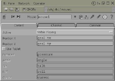
Our basic structure is as follows. We chose to port through the Mouse CHOP, due to our limited knowledge of MIDI's and their outputs. First set the driver to control your cursor. Either pointer if you have an IR sensor, or set it to tilt and roll for axis control. Use a Mouse CHOP in the motion and audio tab. In its parameters Set Activate to While Playing.
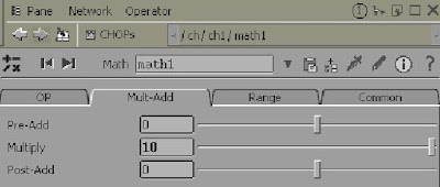
In order to deal with the screen edges, make a Math CHOP, and multiply your input variables by your own preferences.
Connect to a Record CHOP, to capture your movements in real time. Finally, connect the Record CHOP to an Export CHOP. In the Export node you can take the X and Y coordinates to any Node variables you wish from SOPs, POPs, DOPs, etc. (Such as transformation, rotation, etc.)

Post-Mortem
In hindsight, the WiiMote was nothing more than a gimmick. We originally thought that due to its ingenuity and unique control scheme it could help revoloutionize how we interact with a three dimensional environments. Due to the current functionalty of the drivers offered for the WiiMote, it has little more functionality than a custom Mouse/Keyboard. Also due to limitations of the drivers it will only accept one keypress at a time, and does not register multiple buttons correctly on the actual remote (nunchuck/power button).
Originally we wanted to use the WiiMote in the DOPS network to control environment/object variables. Houdini however was not designed with real time dynamics simulation in mind with live inputs, and we ran into technical snags at every turn. For example. We used the WiiMote to control a plane's tilt and roll values with a ball dropped on said surface and a gravity force applied. The simulation looked as if it were working correctly until we discovered that if you changed the angle of the plane too violently the sphere would be instantly forced through said surface and we were unable to find a solution. Instead we cheated and used a particle network to recreate a simple ball maze.
Our next attempt was to use the WiiMote as a custom Interface device. We were able to map scripts and keypresses to the existing WiiMote buttons. It worked swimmingly until we tried to pan zoom or Rotate, where we discovered that multiple keypresses were not supported by the drivers we were using. Making complex interactions in Houdini nearly impossible for our purposes.
Conclusion
In conclusion, our WiiMote project was informitave but due to our limited time frame and knowledge of computer peripherals we were unable to create adequate work arounds that would make the WiiMote more usefull or innovative than the standard mouse and keyboard. Perhaps under future builds of drivers the WiiMotes usefulness in 3d environments may be much more substantial. With more knowledge, and understanding of the drivers, we could make "The Tool" for 3d scene navigation and interaction.
+ LinksWiiLi.orgList of Compatible Bluetooth DevicesWiinRemoteYouTube Video - WiiHoudinii (our inspiration)